| Precast
Segmental Construction |
|||
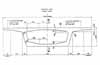
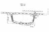
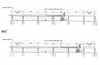
| X-section of Segment | Shear Key Arrangement | Movement Joints | Cantilever Erection |
 |
 |
 |
|
The North Contract consists of a 2.7km long continuous dual 3-lane viaduct carrying the expressway mainline. The viaduct was designed and constructed using the precast segmental balanced cantilever method. The deck was formed from precast segments which were manufactured at the casting yard and joined together at their final positions. Construction of the deck started from the top of each pier, with precast segments added progressively, working away from the pier in a symmetrical manner in order to maintain balance. This enabled deck erection to proceed simultaneously on several piers, resulting in a very fast rate of construction. The viaduct was designed to give a high degree of standardization in the construction. It is divided typically into 236.6m long elements, continuous over six spans between movement joints. These elements repeat themselves to form the entire expressway viaduct. The typical internal span lengths are 42.3m and end spans vary between 30.4m and 37.0m. The internal span was maintained constant as far as possible while by adjusting the end span to accommodate obstructions. Construction Method SelectionThe design process of the viaduct considered cost, construction time and availability of resources. A number of structural options including conventional in situ construction, precast beams or precast segmental construction were considered preliminary. Precast segmental construction was finally chosen for the following reasons (Ng, Morris, Wong & Tornet, 1996):
Furthermore, a comparison of the effects of in situ construction and precast construction on the prestressing force was estimated. Savings by using precast construction:
Loss by using precast construction:
There was a net increase of 17% in prestress for the segmental deck in the estimate. This extra cost was compensated by the savings in longitudinal reinforcement and, more importantly, the savings in reduced casting and construction cost due to the repetitive nature of factory pre-casting and deck erection. Erection Segments for the main carriageway were erected using a 90 tonne portal gantry crane which ran on rail tracks laid along the route of the viaduct. The portal crane had sufficient span over the twin boxes of the mainline, which allowed erection of two S7.2 segments side by side. The smaller slip road deck segments were erected using crawler cranes. The typical erection rate was one carriageway span per week. Segment erection commenced in June 1994 and was completed by October 1995, in 17 months. The segments were transport to the erection area by delivery trailer. A lifting spreader beam controlled by the gantry or crane was used to lift the segment to its final position. The spreader beam was not released until the temporary pre-stressing bars were fixed. The bars were located at the top slab between webs, tips of the wing and bottom slab. For pier segment, the spreader beam was released after the installation of the four vertical pre-stressing bars through the segment and coupled to the anchors on the column head. During the erection of a segment onto a cantilever, epoxy was applied to the joint faces to lubricate the surfaces during segment positioning and to seal the joint against water ingress and transfer shear forces after the epoxy had hardened. The epoxy also sealed the joint to prevent grout loss during the grouting of the internal post-tensioned tendons. After positioning the segments, and before the epoxy hardened, the joint was put into compression by the use of temporary pre-stressing bars. These bars were also used to support the cantilevered segments until the permanent pre-stressing cantilever tendons were stressed. Adjacent cantilevers were then joined together by in situ concrete stitches to form typical six span units. The permanent pre-stressing tendons were arranged into two groups, those used during the cantilevering process (cantilever tendons) and those that were installed after casting the in situ stitch (supplemental tendons). These tendons were anchored in blisters in the internal corners of the box. During the construction, vertical and horizontal adjustments of the cantilever profile if necessary were achieved by using the vertical jacks located on the temporary supports. The in situ stitch was cast after the erection of the last segments of the two cantilevers to be joined. Two clamping beams were fixed across the top slab of the segments of each cantilevers to prevent relative displacement of these cantilevers during casting, concrete setting and post-tensioning works. |
|||